
R055-A13-01
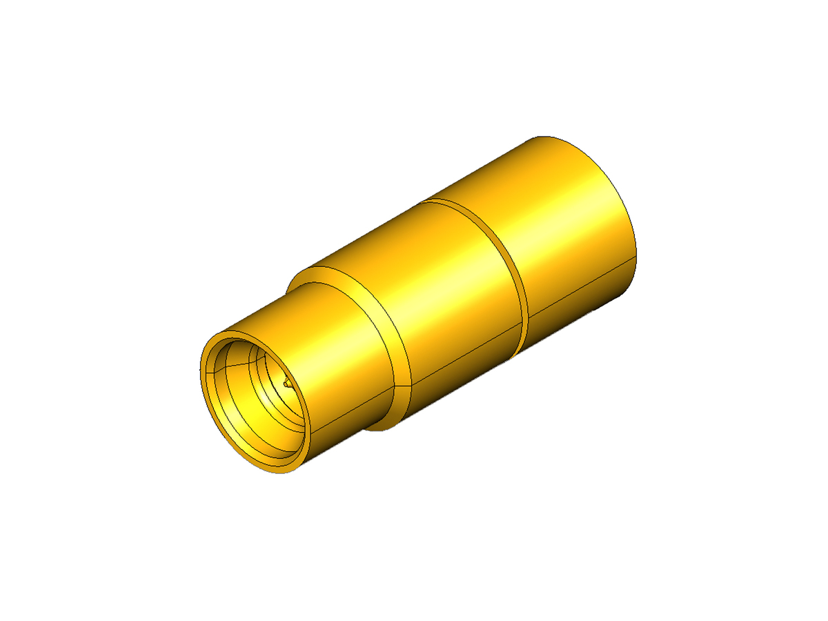
G3PO Male Load 50 Ohm Load, Full Detent, 0.258 Length
General Specifications
| Product Number | R055-A13-01 |
| EAN Code | 4056418769332 |
| Finish, Contacts | Gold plated per MIL-G-45204, Type I, Grade C, Class 1, Over Nickel Plate per SAE AMS-QQ-N-290 |
| Materials, Outer Contacts | Beryllium Copper per ASTM B196 and or/ASTM B197 |
| Materials, Springs | 17-7 Stainless Steel per ASTM A313-95A |
| Finish, Bodies | Gold plated per MIL-G-45204, Type I, Grade C, Class 1, Over Nickel Plate per SAE AMS-QQ-N-290 |
| Materials, Center Contacts | Beryllium Copper per ASTM B196 and or/ASTM B197 |
| Impedance | 50 Ω |
| Materials, Insulators | PTFE Fluorocarbon per ASTM D1710 |
| Frequency Range | DC to 100 GHz typ. |
| Materials, Bodies | Beryllium Copper per ASTM B196 and or/ASTM B197 |
| Product Type | Loads |
Design
| Diameter A | 2.184 mm (0.09 in) |
| Diameter B | 2.642 mm (0.1 in) |
Mechanical Specifications
| Typical Force to Engage / Disengage FD | 2.5 lbs / 4.5 lbs |
| Typical Force to Engage / Disengage SB | 1.2 lbs / 1 lbs |
| Mate / Demate Cycles | 100 |
| Tolerated Misalignment Axial | 0.010 (flush to 0.010 from reference plane) |
| Tolerated Misalignment Radial | ± 0.010 |
| Force to Engage / Disengage LD | 2.5 lbs. typical / 4.5 lbs. typical |
Electrical Specifications
| VSWR | 1.10:1 to 26.5 GHz, 1.25:1 to 65 GHz |
| Insertion Loss-S | 03 √f (GHz) |
| Contact Resistance - Inner Conductor | 6 mΩ |
| Contact Resistance - Outer Conductor | 2 mΩ |
| Insulation Resistance | 3500 megohms minimum |
| DWV at Sea Level | 250 Vrms |
| RF Leakage | -80 dB to 3 GHz, -65 dB to 26.5 GHz |
Designed to accommodate both radial and axial misalignment with negligible voltage standing wave radio (VSWR) change
Meets all MIL-STD Performance specifications
Center-to-center spacing of 0.085-in and board-to-board spacing of 0.120-in are available for increased package density
Frequency from DC to 100 GHz